
Hydraulic Oil Tank Capacity Calculation Formula
Pick the wrong tank size and your hydraulic system will tell you — usually through overheating, foaming, or a pump that sounds like it’s chewing gravel.
The hydraulic oil tank capacity calculation formula isn’t complicated, but a surprising number of systems get it wrong. They use a tank that’s too small, skip the geometry math entirely, or just copy whatever the previous system had. None of those approaches work reliably.
This guide covers everything you need: the right formula, how to calculate volume in gallons or litres, how to handle rectangular and square tank shapes, and how to apply it all to hydraulic tank design calculations that actually hold up in the field.
Why Getting Tank Capacity Right Is Non-Negotiable
Your hydraulic reservoir does more than store oil. It’s the thermal buffer, the deaeration chamber, and the contamination settling zone for your entire system — all at once.
When the tank is too small, oil cycles through the system too fast. There’s no time for heat to dissipate, air bubbles to escape, or particles to settle. You end up with hot, foamy, contaminated fluid hammering through your pump and valves. That’s not a performance problem — it’s a hardware destruction problem.
Get the hydraulic oil tank capacity calculation right, and everything downstream performs better and lasts longer.
The Hydraulic Oil Tank Capacity Calculation Formula
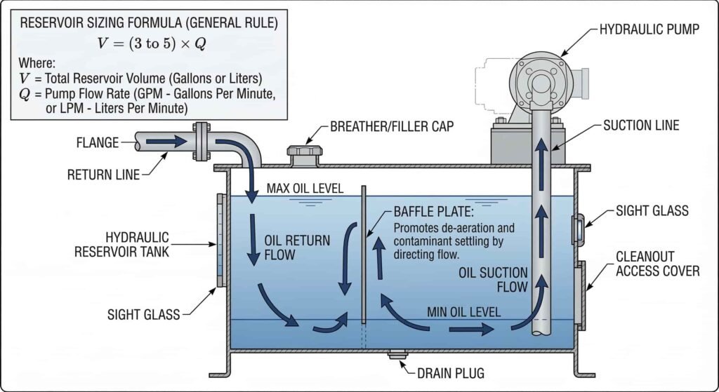
The standard formula used across the industry starts with your pump’s flow rate:
Reservoir Volume = Pump Flow Rate (GPM) × 3 to 5
If your pump moves 20 GPM, your target tank size is:
- Minimum: 20 × 3 = 60 gallons
- Recommended: 20 × 5 = 100 gallons
The 3–5 multiplier gives your oil roughly 3 to 5 minutes of dwell time in the tank per cycle. That’s enough time for heat transfer, air separation, and particle settling — assuming the tank is designed correctly on the inside too (more on that below).
Use the lower multiplier for light-duty systems in cool, controlled environments. Use the upper end — or beyond — for continuous-duty systems, outdoor equipment, or anything running above 3,000 PSI consistently.
How to Calculate Hydraulic Tank Volume by Shape
Once you know your target volume in gallons, you need to confirm the physical tank geometry actually delivers that capacity. This is where the volume math comes in — and it’s the same math whether you’re working with hydraulic oil or water.
Rectangular Tank Volume Calculator (Litres and Gallons)
Most hydraulic reservoirs are rectangular. Here’s the formula:
Volume = Length × Width × Height
All dimensions in the same unit (inches, centimeters, etc.), then convert the result.
Example — Rectangular Tank:
- Length: 36 inches
- Width: 18 inches
- Height: 20 inches
Volume = 36 × 18 × 20 = 12,960 cubic inches
Convert to gallons: 12,960 ÷ 231 = 56.1 gallons
Convert to litres: 12,960 cubic inches × 0.016387 = 212.4 litres
So a 36″ × 18″ × 20″ rectangular tank holds about 56 gallons or 212 litres. If you need 75 gallons, you’d need to adjust one or more dimensions upward.
If you’re working in centimeters instead:
Volume (litres) = Length (cm) × Width (cm) × Height (cm) ÷ 1,000
That’s the rectangular tank volume calculator in litres — straightforward once you keep your units consistent.
Square Tank Volume Calculator
A square tank is just a rectangular tank where length and width are equal. Same formula, just cleaner numbers.
Volume = Side × Side × Height
Example — Square Tank:
- Side: 24 inches
- Height: 30 inches
Volume = 24 × 24 × 30 = 17,280 cubic inches
Convert to gallons: 17,280 ÷ 231 = 74.8 gallons Convert to litres: 17,280 × 0.016387 = 283.1 litres
That square tank gives you just under 75 gallons — which works as a minimum for a 15 GPM pump system using the 5x multiplier.
Quick Unit Conversion Reference
| From | To | Multiply by |
|---|---|---|
| Cubic inches | Gallons | ÷ 231 |
| Cubic inches | Litres | × 0.016387 |
| Gallons | Litres | × 3.785 |
| Litres | Gallons | × 0.2642 |
| Cubic cm | Litres | ÷ 1,000 |
| Cubic feet | Gallons | × 7.481 |
Keep this handy — you’ll use it constantly when cross-referencing a tank gallon calculator result against a metric spec sheet.
Hydraulic Tank Design Calculations: Beyond Just Volume
Volume is the starting point, not the finish line. Good hydraulic tank design calculations account for several factors that volume alone doesn’t cover.
Usable Volume vs. Total Capacity
Never fill a hydraulic tank to 100% of its calculated volume. You need headspace for:
- Thermal expansion — hydraulic oil expands as it heats up
- Return surges — cylinders and actuators dump fluid back into the tank when they retract
- Air cushion — the space above the fluid helps with deaeration
The standard practice is to design so that your usable operating volume is 80% of total tank capacity.
So if you need 75 gallons of usable oil:
75 ÷ 0.80 = 93.75 gallons total → round up to a 100-gallon tank
Cylinder Return Volume
When a large cylinder retracts, it displaces a significant amount of oil back into the reservoir. You need to make sure your tank can absorb that volume without overflowing.
Formula for cylinder displacement:
Volume = π × (Bore Radius)² × Stroke Length
Example:
- Bore: 5 inches (radius = 2.5 inches)
- Stroke: 30 inches
Volume = 3.14159 × (2.5)² × 30 = 3.14159 × 6.25 × 30 = 589 cubic inches
589 ÷ 231 = 2.55 gallons per stroke
On a fast-cycling system, that’s oil sloshing back and forth with every cycle. Your tank needs the physical capacity to handle it without overflowing at the high end or starving the pump at the low end.
Baffle Placement
A properly designed hydraulic reservoir has a baffle — an internal divider — that separates the return port from the suction port. This forces returning oil to travel the full length of the tank before it gets pulled back into the pump.
Without a baffle, hot and aerated oil short-circuits straight back to the pump. The tank volume doesn’t matter if the fluid can bypass all of it.
The baffle should be:
- Positioned roughly in the middle of the tank length
- Tall enough to prevent oil from flowing over the top (leave a gap at the bottom for flow, not the top)
- Angled slightly to direct flow away from the suction port
Port Locations Matter
- Return port: Should discharge below the fluid surface at an angle, directing flow toward the tank wall to reduce turbulence and foaming
- Suction port: Positioned at least 1–2 inches off the tank floor to avoid pulling up settled sediment, and as far from the return port as the baffle allows
- Drain: Full-tank drain at the lowest point for complete fluid changes and cleanout
- Breather/filler: At the top, with a filter rated for the cleanliness level your system requires
Full Worked Example: Hydraulic Tank Design Calculations
Let’s put it all together with a real-world scenario.
System Specs:
- Pump flow rate: 18 GPM
- Operating pressure: 2,800 PSI
- Duty cycle: Continuous, 12 hours/day
- Environment: Outdoor, hot summers
- Main cylinder: 4-inch bore, 36-inch stroke
Step 1 — Base volume using the capacity formula
Continuous duty + hot environment = use the 5x multiplier
18 × 5 = 90 gallons
Step 2 — Account for usable volume headspace
90 ÷ 0.80 = 112.5 gallons total → target a 115–120 gallon tank
Step 3 — Calculate cylinder return volume
Volume = π × (2″)² × 36″ = 3.14159 × 4 × 36 = 452 cubic inches 452 ÷ 231 = 1.96 gallons per stroke
Manageable — but confirm your tank has at least 5–6 gallons of buffer above the normal operating level.
Step 4 — Work out physical dimensions
You need roughly 115 gallons. Let’s find a rectangular tank that delivers it:
Target: 115 gallons × 231 = 26,565 cubic inches
Try: 48″ × 24″ × 24″ = 27,648 cubic inches → 27,648 ÷ 231 = 119.7 gallons ✓
That’s a 48″ × 24″ × 24″ rectangular tank — a common fabrication size — that gives you approximately 120 gallons total, 96 gallons usable. That works.
In litres: 27,648 × 0.016387 = 453 litres total, roughly 362 litres usable
When You Need a Custom-Fabricated Hydraulic Tank
Off-the-shelf tanks work fine for standard applications. But if your system has tight space constraints, unusual port configurations, or demanding operating conditions, a custom hydraulic reservoir tank is usually the smarter call.
With a custom tank, you can spec exactly:
- The dimensions that fit your available mounting envelope
- Port sizes and locations matched to your plumbing
- Built-in baffles, cleanout access, sight glass, and temperature gauge provisions
- Material — carbon steel for most industrial applications, stainless for food-grade or corrosive environments, aluminum for weight-sensitive mobile equipment
- Secondary features like low-level switches, drain valves, or heat exchanger taps welded in from the start
When you work with a fabricator, bring your hydraulic oil tank capacity calculation with you — pump GPM, operating pressure, duty cycle, cylinder specs, and environment. A good fabricator will check your numbers and help you land on the right physical design.
Frequently Asked Questions
The standard formula is: Reservoir Volume = Pump Flow Rate (GPM) × 3 to 5. This gives you the minimum and recommended tank volume in gallons. Adjust toward the higher multiplier for continuous-duty systems, high-pressure applications, or hot operating environments.
Multiply cubic inches by 0.016387 to get litres, or multiply gallons by 3.785. For a tank measured in centimeters: Length × Width × Height ÷ 1,000 gives you litres directly. The rectangular tank volume calculator in litres works the same way as the gallon version — just use the right conversion at the end.
Multiply Length × Width × Height in the same unit (inches or centimeters). Divide by 231 for gallons, or multiply by 0.016387 for litres. Always remember to design your usable volume at 80% of that total to leave room for thermal expansion and return fluid surges.
A square tank has equal length and width. The formula is: Side × Side × Height. From there, apply the same conversions — divide by 231 for gallons, or multiply cubic inches by 0.016387 for litres.
Using the standard formula: 10 × 3 = 30 gallons minimum, 10 × 5 = 50 gallons recommended. For a light-duty intermittent system, 30 gallons may be sufficient. For continuous-duty or outdoor use, go with 50 gallons or add supplemental cooling.
Yes — an oil cooler (heat exchanger) can partially compensate for a smaller reservoir. That said, you still need enough volume to handle return fluid from actuators and to allow adequate deaeration. Most engineers recommend staying above a 2x multiplier even with active cooling in place.
Total capacity is the full geometric volume of the tank. Usable volume is what you actually operate with — typically 75–80% of total. The remaining 20–25% provides headspace for thermal oil expansion, air cushion, and surges from cylinder return strokes.
The Bottom Line
The hydraulic oil tank capacity calculation formula is simple: multiply your pump’s GPM by 3 to 5. But the real work is in applying that number to your actual geometry, accounting for usable volume, cylinder return flow, and the physical design of the tank itself.
Get those hydraulic tank design calculations right upfront, and you’ll build a system that runs cooler, lasts longer, and doesn’t become a recurring maintenance problem.
If you need a custom hydraulic reservoir tank fabricated to your exact specs — any size, any configuration — our team at HydroFuelTanks builds and ships custom tanks to customers nationwide. Get a quote here and we’ll help you nail the sizing from the start.